EP0070139A1 - Bogenabtastungs-Ultraschall-Abbildungsanordnung unter Verwendung von einer Zerstreuungslinse und eines Weglängenkompensators - Google Patents
Bogenabtastungs-Ultraschall-Abbildungsanordnung unter Verwendung von einer Zerstreuungslinse und eines Weglängenkompensators Download PDFInfo
- Publication number
- EP0070139A1 EP0070139A1 EP82303548A EP82303548A EP0070139A1 EP 0070139 A1 EP0070139 A1 EP 0070139A1 EP 82303548 A EP82303548 A EP 82303548A EP 82303548 A EP82303548 A EP 82303548A EP 0070139 A1 EP0070139 A1 EP 0070139A1
- Authority
- EP
- European Patent Office
- Prior art keywords
- path
- acoustic
- energy
- compensating
- imaging system
- Prior art date
- Legal status (The legal status is an assumption and is not a legal conclusion. Google has not performed a legal analysis and makes no representation as to the accuracy of the status listed.)
- Granted
Links
Images


Classifications
-
- G—PHYSICS
- G01—MEASURING; TESTING
- G01S—RADIO DIRECTION-FINDING; RADIO NAVIGATION; DETERMINING DISTANCE OR VELOCITY BY USE OF RADIO WAVES; LOCATING OR PRESENCE-DETECTING BY USE OF THE REFLECTION OR RERADIATION OF RADIO WAVES; ANALOGOUS ARRANGEMENTS USING OTHER WAVES
- G01S7/00—Details of systems according to groups G01S13/00, G01S15/00, G01S17/00
- G01S7/52—Details of systems according to groups G01S13/00, G01S15/00, G01S17/00 of systems according to group G01S15/00
- G01S7/52017—Details of systems according to groups G01S13/00, G01S15/00, G01S17/00 of systems according to group G01S15/00 particularly adapted to short-range imaging
- G01S7/52023—Details of receivers
- G01S7/52033—Gain control of receivers
-
- G—PHYSICS
- G10—MUSICAL INSTRUMENTS; ACOUSTICS
- G10K—SOUND-PRODUCING DEVICES; METHODS OR DEVICES FOR PROTECTING AGAINST, OR FOR DAMPING, NOISE OR OTHER ACOUSTIC WAVES IN GENERAL; ACOUSTICS NOT OTHERWISE PROVIDED FOR
- G10K11/00—Methods or devices for transmitting, conducting or directing sound in general; Methods or devices for protecting against, or for damping, noise or other acoustic waves in general
- G10K11/18—Methods or devices for transmitting, conducting or directing sound
- G10K11/26—Sound-focusing or directing, e.g. scanning
- G10K11/30—Sound-focusing or directing, e.g. scanning using refraction, e.g. acoustic lenses
-
- G—PHYSICS
- G10—MUSICAL INSTRUMENTS; ACOUSTICS
- G10K—SOUND-PRODUCING DEVICES; METHODS OR DEVICES FOR PROTECTING AGAINST, OR FOR DAMPING, NOISE OR OTHER ACOUSTIC WAVES IN GENERAL; ACOUSTICS NOT OTHERWISE PROVIDED FOR
- G10K11/00—Methods or devices for transmitting, conducting or directing sound in general; Methods or devices for protecting against, or for damping, noise or other acoustic waves in general
- G10K11/18—Methods or devices for transmitting, conducting or directing sound
- G10K11/26—Sound-focusing or directing, e.g. scanning
- G10K11/34—Sound-focusing or directing, e.g. scanning using electrical steering of transducer arrays, e.g. beam steering
- G10K11/341—Circuits therefor
- G10K11/346—Circuits therefor using phase variation
Definitions
- the present invention relates to an ultrasonic imaging system for medical diagnostic purposes, and in particular for an arc scan ultrasonic imaging system having a diverging lens and a path-length compensator which compensates for different amounts of acoustic energy loss encountered as the acoustic beam is angulated at different angles.
- Ultrasonic transducer arrays are broadly classified under the categories of linear scan type and sector scan type.
- Conventional linear scan type arrays comprise piezoelectric transducers, typically 256 in number, which are successively arranged in side by side relation to form a linear array.
- a group of 16 transducers is selectively activated by delayed burst pulses generated by a commonly shaed transmit circuitry so that a focused ultrasonic beam is transmitted.
- the selected group is successively shifted to the next by at least one transducer element to shift the beam linearly along the array, so that the beam is scanned in a rectangular format.
- One advantage of the linear scan imaging system relate to the fact that it permits the transmit and receive circuits to be used on a time shared basis. Another advantage is that the linear system provides detailed near-field tomographic images.
- the linear scan system has a disadvantage in that it is incapable of scanning areas behind ribs and the transducer array is itself too bulky for handling.
- the transducer array of conventional sector scan systems usually comprise 32 transducer elements each of which is associated with its own transmit and receive circuitry.
- the beam is steered in a sector format by the transmit circuit which applies successively delayed pulses.
- the sector scan system is capable of imaging the behind-the-rib areas, the control circuitry is complex and the acoustic beams cluster near the apex of the sector to such a degree that useful tomographic information is not obtained.
- the present invention is therefore to provide a transducer array having transducers arranged on a curved surface for emission of diverging beams of acoustic energy and an acoustic diverging lens for increasing the angle of divergence of the emitted acoustic beams in order to take advantages of the linear and sector scan formats.
- the acoustic diverging lens has different path-lengths along the array so that the acoustic energy from different transducers differs in amplitude depending on the point of transmission.
- the provision of the diverging lens thus results in a tomographic image having different intensities depending on the point of transmission of acoustic energy.
- an object of the present invention is to provide an ultrasonic imaging system for analyzing the internal structure of a body by acoustic energy which compensates for the differences in acoustic energy level arising from the differing path-length of the lens.
- the ultrasonic imaging system comprises a transducer array including a plurality of elongated piezoelectric transducers successively arranged along a curved surface for emission of diverging beams of acoustic energy, an acoustic diverging lens affixed to the curved surface and formed of a material having an acoustic impedance substantially equal to the acoustic impedance of the body and a lower sound velocity than the sound velocity of the body for increasing the angle of divergence of the emitted acoustic energy.
- the system further includes a source for successively generating burst energy, and means for selectively establishing a connection from the energy source to a subarray of the transducers to transmit a beam of acoustic energy therefrom and shifting the connection to the next subarray by at least one transducer in response to the generation of subsequent acoustic energy to cause the emitted acoustic energy to be angulated in an arc scan format.
- the present invention is characterized by the provision of means for compensating for differences in energy level resulting from the differences in the path-length of the acoustic lens.
- the compensating means generates a path-length compensating signal of which the magnitude varies as a function of the point of transmission of acoustic beam on the transducer array and modulates the energy level according to the compensating signal.
- a ramp generator for periodically generating in response to the generation of burst energy a ramp voltage which increases as a function of time. This ramp voltage is combined with the path-length compensating signal for modulating the level of return echo signals.
- a ramp generator for periodically generating a ramp voltage in response to the burst energy.
- the time of generation of the ramp voltage is delayed as a function of the path-length compensating signal.
- the return echo signal is modulated in amplitude according to the instantaneous value of the delayed ramp voltage.
- the transducer array 10 comprises a conductive frame 11 which is convexed in the direction of propagation of ultrasonic energy.
- a plurality of elongated piezoelectric transducers 12 is successively arranged on the convexed frame structure 11 as seen from Fig. 2.
- each transducer 12 comprises a piezoelectric element 20 which extends transverse to the frame 11 to bridge its parallel side members and connected thereto by a suitable adhesive material.
- electrodes 21 and 22 are electrodes 21 and 22, respectively.
- each piezoelectric element 20 is so dimensioned that its width-to-thickness ratio imparts a transverse expansion vibrational mode to the array 10. With this vibrational mode a high sensitivity and excellent bandwidth characteristics are obtained.
- each transducer 12 includes a first impedance matching element 23 which is attached to the lower electrode 22. The transducers 12 are secured to a second, or common impedance matching layer 24 which extends along the length of the frame 11 in contact with the first impedance matching elemtns 23.
- Suitable material for the first impedance matching elements 23 is rock crystal, glass or fused quartz and suitable material for the second impedance matching layer 24 is epoxy resin.
- the acoustic impedance of the first impedance matching elements 23 is preferably 2.5 to 9.5 times greater than the acoustic impedance of the human body and the acoustic impedance values of the common impedance matching layer 24 is preferably 1.6 to 2.7 times greater than that of the human body.
- a diverging acoustic lens 30 generally of a plano-concave construction is secured to the common impedance matching layer 24 with its plane surface facing toward the human body to define an entry surface for the generated ultrasonic energy.
- the acoustic lens 30 is formed of silicon or silicon compound having substantially the same acoustic impedance as the human body but having such an acoustic property that in the lens 30 the acoustic energy propagates at a speed lower than it propagates in the human body. Because of the increase in sound velocity in the human body, the incident ultrasonic beam is deflected in a direction away from the normal to the array 10 as it impinges on the plane entry surface at an angle thereto as illustrated in Fig. 5, and therefore the scanned beam propagates as if it originates from a point 31 closer to the array 10 rather than from a point 32 from which it would originate if the acoustic lens 30 is not provided.
- the amount of tomographic information available from the arc scan transducer array of the invention is thus greater than that available with conventional linear scan type arrays.
- the plane entry surface difined by the acoustic lens 30 assures an intimate contact with the human subject, so that acoustic energy encounters no loss upon entry into and return from the human body. It is seen from Fig. 3 that the acoustic lens 3 preferably has a convexed radiating surface as viewed in the longitudinal direction - of the array to provide beam focusing.
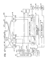
- Fig. 6 is an illustration of a control circuit for driving the transducer array 10 of the invention.
- analog multiplexers 41-1 through 41-16 are provided for the array 10 which includes transducers #1 through #128. These transducers are divided into 16 subgroups of eight transducers each.
- Each analog multiplexer 41 is provided with eight output terminals for connection to those transducers which are spaced by sixteen elements, with the corresponding output terminals of the multiplexers being connected respectively to adjacent transducers of each transducer group.
- the #1 output terminals of multiplexers 41-1 to 41-16 are connected respectively to the #1 to #16 transducers, the #2 output terminals being connected respectively to the #17 to #32 transducers, and the #16 output terminals being connected respectively to the #113 to #128 transducers.
- Counters 42-1 to 42-16 are connected to the inputs of the multiplexers 41-1 to 41-16 respectively to select one of the eight output terminals of the associated multiplexers in response to output signals supplied individually from a shift register 43 which in turn is connected to receive a clock signal from a clock source 44.
- the counters 42-1 to 42-16 are incremented in response to every 16th clock pulse and cleared by a reset counter 45 in response to every 128th clock pulse.
- a burst of pulses is generated by a pulse generator 48 in response to each clock pulse from source 44.
- the pulse burst is applied to a focusing delay multiplexer 47.
- the multilexer 47 essentially comprises a read only memory from which focusing delay data are retrieved in response to each clock pulse and a plurality of successively arranged variable delay elements which correspond in number to the multiplexers 41-1 to 41-16 to introduce different amounts of delay time to the burst signal in accordance with the data read out of the memory.
- an amplitude modulator 46 comprises a plurality of gain-controlled amplifiers 46-1 to 46-16 arranged to receive the delayed burst signals to modulate the amplitude of each delayed burst signal in response to a gain control signal.
- the outputs of the gain-controlled amplifiers 46-1 to 46-16 are respectively coupled to the input/output terminals of the multiplexers 41-1 to 41-16.
- the gain control signal is derived from a circuit which comprises an address counter 51 coupled to the clock source 44, a read only memory 52 storing path-length compensating data, and a digital-analog converter 53.
- the address counter 51 is incremented by the clock pulse and generates an address code for the read only memory 52.
- the path-length compensation data are read out of the memory 52 in response to each clock pulse.
- the compensation data represent the amplification gains with which the delayed burst signals are amplified to compensate for differences in attenuation between transmitted beams passing through different go-and-return path-lengths of the lens 30. Therefore, the amount of compensensation given to the beam emerging from the edge portions of the lens 30 is maximum and the one given to the beam emerging from the center of the center of the lens is minimum.
- the beam emerging from and returning to any point of the lens 30 has an energy level which would be obtained in the absense of the lens 30.
- the returning acoustic waves are detected by the 16 transducers of the selected subgroup and passed through multiplexers 41-1 to 41-16 to a receiver 49 which processes the return echo into a form suitable for display.
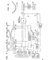
- Figs. 7 and 9 are modified embodiments of the invention in which parts corresponding in function to those in Fig. 6 are designated by corresponding numerals.
- the amplitude modulator 46 is eliminated and the outputs of the focusing delay multiplexer 47 are directly coupled to the input/output terminals of the multiplexers 41-1 to 41-16.
- the embodiment of Fig. 7 employs a receive clock source 60, an address counter 61 for generating an address code in response to each receive clock, a read only memory 62 storing path-length compensating data which are read in response to the address code for application to a digital-analog converter 63.
- the receiver 49 includes buffer amplifiers 62 coupled respectively to the input/output terminals of the multiplexers 41-1 to 41-16, a gain-controlled amplifier 65, a detector 66, a scan converter 67 and a CRT display unit 68.
- the receive clock source 60 generates a clock pulse which is delayed with respect to the transmit clock pulse by an amount sufficient to allow the transmitted acoustic beam to return from different tissues in the human body to the transducer array 10.
- a ramp generator 69 is coupled to the receive clock source 60 to generate a ramp voltage in response to each receive clock pulse. This ramp voltage is applied to an input of an adder 70 where it is summed with a path-length compensating signal from the digital-analog converter 63. As indicated by a dotted curve in Fig. 8, the amplitude of the compensating signal varies nonlinearly as a function of time from a maximum value corresponding to the beam emanating from the edge portions of the lens 30 to a minimum value corresponding to the beam emanating from the center of the lens.
- the combined output of the adder 70 is applied to the control terminal of the gain-controlled amplifier 65 to which a combined echo signal is fed from the buffer amplifiers 64.
- the echo signal is modulated in amplitude by the amplifier 65. Since the ramp voltage increases as a function of time, the amplification gain increases as a function of distance from the array 10, so that echos returning from tissues at greater distances are amplified with a higher gain. Added to this is the path-length compensation provided by the output of the digital-analog converter 63.
- the compensated echo signal is applied to the detector 66 which removes its high frequency components to detect the amplitude variations.
- the scan converter 67 may include an analog-digital converter for converting the analog echo signal to digital echo data and a random access memory in which the digital echo data is written column by column and read out of the memory row by row in such a timing that the arc scan format is converted to a raster scan format.
- the echo data in the raster scan format is converted to a corresponding anlog signal and applied to the display unit 68 to modulate the intensity of a cathode ray beam which is scanned in raster form in a conventional manner to produce a tomographic image.
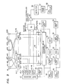
- the embodiment of Fig. 9 provides path-length compensation both for transmission and reception.
- the memory 52 contains transmit path-length compensation data.
- the Fig. 9 embodiment includes a receive clock source 80, an address counter 81 coupled thereto to generate an address signal, a read only memory 82 responsive to the address signal to generate "receive" path-length compensation delay data which are used during receive mode for compensating for the return path-lengths of the lens 30.
- a digital variable delay circuit 83 is coupled to the output of the read only memory 82 and to the receive clock source 80 to introduce a delay time to the receive clock pulse according to the delay data.
- the receive clock pulses are delayed in the delay circuit 83 by a maximum interval Tmax when the echo is received at the center area of the lens 30 and delayed by a minumum, or zero when the echo is received at the peripheral areas. More specifically, the delay time is successively decreased from the maximum to the minimum as the beam is steered in a direction away from the center of the lens 30.
- the delayed pulse is applied to a ramp generator 84 the output of which is coupled to the control terminal of the gain-controlled amplifier 65.
- the echo returning on a path 100 rises on a middle portion of a ramp voltage 90 which is generated in response to a receive clock 91 delayed by t l
- the echo returning along a path 101 rises on a portion near the lower edge of a ramp 92 which is generated in response to a clock 93 delayed by t 2' and so on.
- the echo signal supplied from the buffer amplifers 64 is amplified with higher gains for echos passing through greater path-lengths of the lens 30.
- the embodiment of Fig. 9 is advantageous if the lens 30 imparts such a large value attenuation to the passing energy that the amount of compensation provided only for transmission or reception is insufficient.
Applications Claiming Priority (2)
| Application Number | Priority Date | Filing Date | Title |
|---|---|---|---|
| JP56106802A JPS587231A (ja) | 1981-07-07 | 1981-07-07 | 超音波診断装置 |
| JP106802/81 | 1981-07-07 |
Publications (2)
| Publication Number | Publication Date |
|---|---|
| EP0070139A1 true EP0070139A1 (de) | 1983-01-19 |
| EP0070139B1 EP0070139B1 (de) | 1986-03-19 |
Family
ID=14442994
Family Applications (1)
| Application Number | Title | Priority Date | Filing Date |
|---|---|---|---|
| EP19820303548 Expired EP0070139B1 (de) | 1981-07-07 | 1982-07-06 | Bogenabtastungs-Ultraschall-Abbildungsanordnung unter Verwendung von einer Zerstreuungslinse und eines Weglängenkompensators |
Country Status (3)
| Country | Link |
|---|---|
| EP (1) | EP0070139B1 (de) |
| JP (1) | JPS587231A (de) |
| DE (1) | DE3269968D1 (de) |
Cited By (7)
| Publication number | Priority date | Publication date | Assignee | Title |
|---|---|---|---|---|
| EP0239167A1 (de) * | 1986-03-28 | 1987-09-30 | Laboratoires D'electronique Et De Physique Appliquee L.E.P. | Apodisierter Ultraschallechograf mit einer linearen Anordnung piezoelektrischer Wandler und Verfahren zur Realisierung einer solchen Anordnung |
| EP0239999A2 (de) * | 1986-04-02 | 1987-10-07 | Matsushita Electric Industrial Co., Ltd. | Ultraschallwandler mit einem Ultraschallfortpflanzungsmedium |
| FR2628265A1 (fr) * | 1987-03-06 | 1989-09-08 | Thomson Csf | Antenne directive a transducteurs multiples notamment pour sonar |
| FR2650144A1 (fr) * | 1989-07-19 | 1991-01-25 | Commissariat Energie Atomique | Traducteur ultrasonore focalise |
| EP0498524A2 (de) * | 1991-02-06 | 1992-08-12 | GEC-Marconi Limited | Detektorsystem |
| FR2686457A1 (fr) * | 1992-01-17 | 1993-07-23 | Thomson Csf | Antenne a balayage electronique. |
| WO2015105977A1 (en) * | 2014-01-09 | 2015-07-16 | Baker Hughes Incorporated | Devices and methods for downhole acoustic imaging |
Families Citing this family (2)
| Publication number | Priority date | Publication date | Assignee | Title |
|---|---|---|---|---|
| JPS63220847A (ja) * | 1987-03-10 | 1988-09-14 | 松下電器産業株式会社 | 超音波探触子 |
| CN113295777B (zh) * | 2021-04-07 | 2023-04-28 | 聚融医疗科技(杭州)有限公司 | 一种基于透镜回波的提升谐波成像性能的方法及系统 |
Citations (9)
| Publication number | Priority date | Publication date | Assignee | Title |
|---|---|---|---|---|
| US4043181A (en) * | 1975-04-18 | 1977-08-23 | New York Institute Of Technology | Ultrasonic pulse-echo apparatus |
| US4140107A (en) * | 1972-12-28 | 1979-02-20 | Erasmus University Rotterdam | Echoscope for examination of objects |
| GB2011075A (en) * | 1977-12-27 | 1979-07-04 | Gen Electric | Ultrasonic imaging systems |
| GB2016143A (en) * | 1978-03-09 | 1979-09-19 | Gen Electric | Sector scan ultrasonic imaging system |
| GB2021767A (en) * | 1978-05-30 | 1979-12-05 | Matsushita Electric Ind Co Ltd | Two-dimensional linear b-scan ultrasonic diagnostic apparaus with phase and amplitude tapering |
| US4183249A (en) * | 1975-03-07 | 1980-01-15 | Varian Associates, Inc. | Lens system for acoustical imaging |
| USRE30443E (en) * | 1977-04-25 | 1980-12-09 | Krautkramer-Branson, Incorporated | Real-time ultrasonic imaging apparatus |
| US4281550A (en) * | 1979-12-17 | 1981-08-04 | North American Philips Corporation | Curved array of sequenced ultrasound transducers |
| GB2079102A (en) * | 1980-06-27 | 1982-01-13 | Matsushita Electric Ind Co Ltd | Arc scan transducer array having a diverging lens |
Family Cites Families (1)
| Publication number | Priority date | Publication date | Assignee | Title |
|---|---|---|---|---|
| JPS57209044A (en) * | 1981-06-19 | 1982-12-22 | Olympus Optical Co | Ultrasonic diagnostic apparatus for body cavity |
-
1981
- 1981-07-07 JP JP56106802A patent/JPS587231A/ja active Granted
-
1982
- 1982-07-06 EP EP19820303548 patent/EP0070139B1/de not_active Expired
- 1982-07-06 DE DE8282303548T patent/DE3269968D1/de not_active Expired
Patent Citations (9)
| Publication number | Priority date | Publication date | Assignee | Title |
|---|---|---|---|---|
| US4140107A (en) * | 1972-12-28 | 1979-02-20 | Erasmus University Rotterdam | Echoscope for examination of objects |
| US4183249A (en) * | 1975-03-07 | 1980-01-15 | Varian Associates, Inc. | Lens system for acoustical imaging |
| US4043181A (en) * | 1975-04-18 | 1977-08-23 | New York Institute Of Technology | Ultrasonic pulse-echo apparatus |
| USRE30443E (en) * | 1977-04-25 | 1980-12-09 | Krautkramer-Branson, Incorporated | Real-time ultrasonic imaging apparatus |
| GB2011075A (en) * | 1977-12-27 | 1979-07-04 | Gen Electric | Ultrasonic imaging systems |
| GB2016143A (en) * | 1978-03-09 | 1979-09-19 | Gen Electric | Sector scan ultrasonic imaging system |
| GB2021767A (en) * | 1978-05-30 | 1979-12-05 | Matsushita Electric Ind Co Ltd | Two-dimensional linear b-scan ultrasonic diagnostic apparaus with phase and amplitude tapering |
| US4281550A (en) * | 1979-12-17 | 1981-08-04 | North American Philips Corporation | Curved array of sequenced ultrasound transducers |
| GB2079102A (en) * | 1980-06-27 | 1982-01-13 | Matsushita Electric Ind Co Ltd | Arc scan transducer array having a diverging lens |
Cited By (11)
| Publication number | Priority date | Publication date | Assignee | Title |
|---|---|---|---|---|
| EP0239167A1 (de) * | 1986-03-28 | 1987-09-30 | Laboratoires D'electronique Et De Physique Appliquee L.E.P. | Apodisierter Ultraschallechograf mit einer linearen Anordnung piezoelektrischer Wandler und Verfahren zur Realisierung einer solchen Anordnung |
| FR2596269A1 (fr) * | 1986-03-28 | 1987-10-02 | Labo Electronique Physique | Echographe ultrasonore apodise a barrette lineaire de transducteurs piezoelectriques et procede de realisation d'une telle barrette |
| EP0239999A2 (de) * | 1986-04-02 | 1987-10-07 | Matsushita Electric Industrial Co., Ltd. | Ultraschallwandler mit einem Ultraschallfortpflanzungsmedium |
| EP0239999A3 (en) * | 1986-04-02 | 1989-03-22 | Matsushita Electric Industrial Co., Ltd. | Ultrasonic probe having an ultrasonic propagation medium |
| US5050128A (en) * | 1986-04-02 | 1991-09-17 | Matsushita Electric Industrial Co., Ltd. | Ultrasonic probe having an ultrasonic propagation medium |
| FR2628265A1 (fr) * | 1987-03-06 | 1989-09-08 | Thomson Csf | Antenne directive a transducteurs multiples notamment pour sonar |
| FR2650144A1 (fr) * | 1989-07-19 | 1991-01-25 | Commissariat Energie Atomique | Traducteur ultrasonore focalise |
| EP0498524A2 (de) * | 1991-02-06 | 1992-08-12 | GEC-Marconi Limited | Detektorsystem |
| EP0498524A3 (en) * | 1991-02-06 | 1993-03-03 | Gec-Marconi Limited | Detection system |
| FR2686457A1 (fr) * | 1992-01-17 | 1993-07-23 | Thomson Csf | Antenne a balayage electronique. |
| WO2015105977A1 (en) * | 2014-01-09 | 2015-07-16 | Baker Hughes Incorporated | Devices and methods for downhole acoustic imaging |
Also Published As
| Publication number | Publication date |
|---|---|
| EP0070139B1 (de) | 1986-03-19 |
| DE3269968D1 (en) | 1986-04-24 |
| JPS587231A (ja) | 1983-01-17 |
| JPS649012B2 (de) | 1989-02-16 |
Similar Documents
| Publication | Publication Date | Title |
|---|---|---|
| US4470308A (en) | Arc scan ultrasonic imaging system having diverging lens and path-length compensator | |
| US4180792A (en) | Transmit-receive transducer array and ultrasonic imaging system | |
| US4224829A (en) | Two-dimensional linear B-scan ultrasound diagnostic apparatus with phase and amplitude tapering | |
| US4241611A (en) | Ultrasonic diagnostic transducer assembly and system | |
| US4305296A (en) | Ultrasonic imaging method and apparatus with electronic beam focusing and scanning | |
| US4180790A (en) | Dynamic array aperture and focus control for ultrasonic imaging systems | |
| US5083568A (en) | Ultrasound diagnosing device | |
| JP4172841B2 (ja) | 超音波イメージング・システム、超音波イメージング・システムを動作させる方法及びマルチプレクサ・マザーボード | |
| EP0062477B1 (de) | Ultraschallmessgerät | |
| US4159462A (en) | Ultrasonic multi-sector scanner | |
| US4208916A (en) | Electronic ultrasonic sector scanning apparatus and method | |
| US3971962A (en) | Linear transducer array for ultrasonic image conversion | |
| US4945915A (en) | Ultrasonic diagnosis apparatus | |
| EP0249965A1 (de) | Ultraschallvorrichtung | |
| JPS6346693B2 (de) | ||
| EP0070139B1 (de) | Bogenabtastungs-Ultraschall-Abbildungsanordnung unter Verwendung von einer Zerstreuungslinse und eines Weglängenkompensators | |
| US4344159A (en) | Ultrasonic transducer | |
| GB2064118A (en) | Ultrasonic imaging system | |
| US5676149A (en) | Method of compensating for inoperative elements in an ultrasound transducer | |
| US5128903A (en) | Ultrasound apparatus for the virtual diminution of the array division of a connectable transducer array | |
| JPH0226189B2 (de) | ||
| JPS6021744A (ja) | 超音波映像装置 | |
| JPH0344773B2 (de) | ||
| JPS63209629A (ja) | 超音波プロ−ブ | |
| JPH0147754B2 (de) |
Legal Events
| Date | Code | Title | Description |
|---|---|---|---|
| PUAI | Public reference made under article 153(3) epc to a published international application that has entered the european phase |
Free format text: ORIGINAL CODE: 0009012 |
|
| AK | Designated contracting states |
Designated state(s): DE FR GB |
|
| 17P | Request for examination filed |
Effective date: 19830701 |
|
| GRAA | (expected) grant |
Free format text: ORIGINAL CODE: 0009210 |
|
| AK | Designated contracting states |
Kind code of ref document: B1 Designated state(s): DE FR GB |
|
| REF | Corresponds to: |
Ref document number: 3269968 Country of ref document: DE Date of ref document: 19860424 |
|
| ET | Fr: translation filed | ||
| PLBE | No opposition filed within time limit |
Free format text: ORIGINAL CODE: 0009261 |
|
| STAA | Information on the status of an ep patent application or granted ep patent |
Free format text: STATUS: NO OPPOSITION FILED WITHIN TIME LIMIT |
|
| 26N | No opposition filed | ||
| PGFP | Annual fee paid to national office [announced via postgrant information from national office to epo] |
Ref country code: DE Payment date: 20010702 Year of fee payment: 20 |
|
| PGFP | Annual fee paid to national office [announced via postgrant information from national office to epo] |
Ref country code: GB Payment date: 20010704 Year of fee payment: 20 |
|
| PGFP | Annual fee paid to national office [announced via postgrant information from national office to epo] |
Ref country code: FR Payment date: 20010712 Year of fee payment: 20 |
|
| REG | Reference to a national code |
Ref country code: GB Ref legal event code: IF02 |
|
| PG25 | Lapsed in a contracting state [announced via postgrant information from national office to epo] |
Ref country code: GB Free format text: LAPSE BECAUSE OF EXPIRATION OF PROTECTION Effective date: 20020705 |
|
| REG | Reference to a national code |
Ref country code: GB Ref legal event code: PE20 Effective date: 20020705 |